Running Linux Mint 18.1 (kernel 4.4.0-53) on a Gigabyte Brix BACE-3160 (with an i915 graphics controller) , I had all kind of minor graphics artifacts (in particular a sluggish mouse pointer and Kodi felt heavy). So obviously, I went for updating the graphics stack.
Intel supplies an tool for doing this automagically on a selected list of distributions. In particular, the Graphics Update Tool 2.0.2 is intended for Ubuntu 16.04. Which is fine, since Mint 18.1 is derived from this distribution exactly.
So I downloaded it, and installed it:
$ sudo dpkg -i intel-graphics-update-tool_2.0.2_amd64.deb
That didn’t work all that nice, because there were missing dependencies. Easily fixed with
$ sudo apt-get -f install
And then launch the tool itself:
$ sudo intel-graphics-update-tool
And this is where the tool refused, because the distribution doesn’t match. So I tricked it by replacing the file it checks (a thanks goes to strace). First, save the real one:
$ sudo mv /etc/lsb-release /etc/lsb-release-mint
and then edit /etc/lsb-release to mimic Ubuntu. That is, saying this:
DISTRIB_ID=Ubuntu
DISTRIB_RELEASE=16.04
DISTRIB_CODENAME=xenial
DISTRIB_DESCRIPTION="Ubuntu 16.04 LTS"
And then run the tool again. Now everything went through fine. And for the record, it really helped with those graphics issues.
By the way, among the things it did was to add an apt-get repository. Namely, adding the file /etc/apt/sources.list.d/intellinuxgraphics.list with the following:
deb https://download.01.org/gfx/ubuntu/16.04/main xenial main #Intel Graphics drivers
For the record, this is /etc/lsb-release for Linux Mint 18.1:
DISTRIB_ID=LinuxMint
DISTRIB_RELEASE=18.1
DISTRIB_CODENAME=serena
DISTRIB_DESCRIPTION="Linux Mint 18.1 Serena"
In case someone needs to fake Linux Mint…
Note that the effective initrd.img file (probably in /boot) must be updated (I’m not 100% about it, but it seems like the update tool did it): Odds are that the kernel modules related to graphics are loaded from the initrd.img, and not /lib/modules, as part of displaying the graphical splash screen (Plymouth) until Gnome is up and running. Unless you’ve disabled it, like myself.
Introduction
In several versions of Xilinx’ wrapper for the integrated PCIe block, it’s the user application logic’s duty to instantiate the module which generates the “pipe clock”. It typically looks something like this:
pcie_myblock_pipe_clock #
      (
          .PCIE_ASYNC_EN                  ( "FALSE" ),                 // PCIe async enable
          .PCIE_TXBUF_EN                  ( "FALSE" ),                 // PCIe TX buffer enable for Gen1/Gen2 only
          .PCIE_LANE                      ( LINK_CAP_MAX_LINK_WIDTH ), // PCIe number of lanes
          // synthesis translate_off
          .PCIE_LINK_SPEED                ( 2 ),
          // synthesis translate_on
          .PCIE_REFCLK_FREQ               ( PCIE_REFCLK_FREQ ),        // PCIe reference clock frequency
          .PCIE_USERCLK1_FREQ             ( PCIE_USERCLK1_FREQ ),      // PCIe user clock 1 frequency
          .PCIE_USERCLK2_FREQ             ( PCIE_USERCLK2_FREQ ),      // PCIe user clock 2 frequency
          .PCIE_DEBUG_MODE                ( 0 )
      )
      pipe_clock_i
      (

          //---------- Input -------------------------------------
          .CLK_CLK                        ( sys_clk ),
          .CLK_TXOUTCLK                   ( pipe_txoutclk_in ),     // Reference clock from lane 0
          .CLK_RXOUTCLK_IN                ( pipe_rxoutclk_in ),
          .CLK_RST_N                      ( pipe_mmcm_rst_n ),      // Allow system reset for error_recovery
          .CLK_PCLK_SEL                   ( pipe_pclk_sel_in ),
          .CLK_PCLK_SEL_SLAVE             ( pipe_pclk_sel_slave),
          .CLK_GEN3                       ( pipe_gen3_in ),

          //---------- Output ------------------------------------
          .CLK_PCLK                       ( pipe_pclk_out),
          .CLK_PCLK_SLAVE                 ( pipe_pclk_out_slave),
          .CLK_RXUSRCLK                   ( pipe_rxusrclk_out),
          .CLK_RXOUTCLK_OUT               ( pipe_rxoutclk_out),
          .CLK_DCLK                       ( pipe_dclk_out),
          .CLK_OOBCLK                     ( pipe_oobclk_out),
          .CLK_USERCLK1                   ( pipe_userclk1_out),
          .CLK_USERCLK2                   ( pipe_userclk2_out),
          .CLK_MMCM_LOCK                  ( pipe_mmcm_lock_out)

      );
Consequently, some timing constraints that are related to the PCIe block’s internal functionality aren’t added automatically by the wrapper’s own constraints, but must be given explicitly by the user of the block, typically by following an example design.
This post discusses the implications of this situation. Obviously, none of this applies to PCIe block wrappers which handle this instantiation internally.
What is the pipe clock?
For our narrow purposes, the PIPE interface is the parallel data part of the SERDES attached to the Gigabit Transceivers (MGTs), which drive the physical PCIe lanes. For example, data to a Gen1 lane, running at 2.5 GT/s, requires 2.0 Gbit/s of payload data (as it’s expanded by a 10/8 ratio with 10b/8b encoding). If the SERDES is fed with 16 bits in parallel, a 125 MHz clock yields the correct data rate (125 MHz * 16 = 2 GHz).
By the same coin, a Gen2 interface requires a 250 MHz clock to support a payload data rate of 4.0 Gbit/s per lane (expanded into 5 GT/s with 10b/8b encoding).
The clock mux
If a PCIe block is configured for Gen2, it’s required to support both rates: 5 GT/s, and also be able to fall back to 2.5 GT/s if the link partner doesn’t support Gen2 or if the link doesn’t work properly at the higher rate.
In the most common setting (or always?), the pipe clock is muxed between two source clocks by this piece of code (in the pipe_clock module):
    //---------- PCLK Mux ----------------------------------
    BUFGCTRL pclk_i1
    (
        //---------- Input ---------------------------------
        .CE0                        (1'd1),
        .CE1                        (1'd1),
        .I0                         (clk_125mhz),
        .I1                         (clk_250mhz),
        .IGNORE0                    (1'd0),
        .IGNORE1                    (1'd0),
        .S0                         (~pclk_sel),
        .S1                         ( pclk_sel),
        //---------- Output --------------------------------
        .O                          (pclk_1)
    );
    end
So pclk_sel, which is a registered version of the CLK_PCLK_SEL input port is used to switch between a 125 MHz clock (pclk_sel == 0) and a 250 MHz clock (clk_sel == 1), both clocks generated from the same MMCM_ADV block in the pipe_clock module.
The BUFGMUX’ output, pclk_1 is assigned as the pipe clock output (CLK_PCLK). It’s also used in other ways, depending on the instantiation parameters of pipe_clock.
Constraints for Gen1 PCIe blocks
If a PCIe block is configured for Gen1 only, there’s no question about the pipe clock’s frequency: It’s 125 MHz. As a matter of fact, if the PCIE_LINK_SPEED instantiation parameter is set to 1, one gets (by virtue of Verilog’s generate commands)
    BUFG pclk_i1
    (
        //---------- Input ---------------------------------
        .I                          (clk_125mhz),
        //---------- Output --------------------------------
        .O                          (clk_125mhz_buf)
    );
    assign pclk_1 = clk_125mhz_buf;
But never mind this — it’s never used: Even when the block is configured as Gen1 only, PCIE_LINK_SPEED is set to 3 in the example design’s instantiation, and we all copy from it.
Instead, the clock mux is used and fed with pclk_sel=0. The constraints reflect this with the following lines appearing in the example design’s XDC file for Gen1 PCIe blocks (only!):
set_case_analysis 1 [get_pins {pcie_myblock_support_i/pipe_clock_i/pclk_i1_bufgctrl.pclk_i1/S0}]
set_case_analysis 0 [get_pins {pcie_myblock_support_i/pipe_clock_i/pclk_i1_bufgctrl.pclk_i1/S1}]
set_property DONT_TOUCH true [get_cells -of [get_nets -of [get_pins {pcie_myblock_support_i/pipe_clock_i/pclk_i1_bufgctrl.pclk_i1/S0}]]]
The first two commands tell the timing analysis tools to assume that the clock mux’ inputs are S0=1 and S1=0, and hence that the mux forwards the 125 MHz clock (connected to I0).
The DONT_TOUCH constraint works around a bug in early Vivado revisions, as explained in AR #62296: The S0 input is assigned ~pclk_sel, which requires a logic inverter. This inverter was optimized into the BUFCTRL primitive by the synthesizer, flipping the meaning of the first set_case_analysis constraints. Which caused the timing tools to analyze the design as if both S0 and S1 were set to zero, hence no clock output, and no constraining of the relevant paths.
The problem with this set of constraints is their cryptic nature: It’s not clear at all why they are there, just by reading the XDC file. If the user of the PCIe block decides, for example, to change from a 8x Gen1 configuration to 4x Gen2, everything will appear to work nicely, since all clocks except the pipe clock remain the same. It takes some initiative and effort to figure out that these constraints are incorrect for a Gen2 block.
To make things even worse, almost all relevant paths will meet the 250 MHz (4 ns) requirement even when constrained for 125 MHz on a sparsely filled FPGA, simply because there’s little logic along these paths. So odds are that everything will work fine during the initial tests (before the useful logic is added to the design), and later on the PCIe interface may become shaky throughout the design process, as some paths accidentally exceed the 4 ns limit.
Dropping the set_case_analysis constraints
As these constraints are relaxing by their nature, what happens if they are dropped? Once could expect that the tools would work a bit harder to ensure that all relevant paths meet timing with either 125 MHz or 250 MHz, or simply put, that the constraining would occur as if pclk_1 was always driven with a 250 MHz clock.
But this isn’t how timing calculations are made. The tools can’t just pick the faster clock from a clock mux and follow through, since the logic driven by the clock might interact with other clock domains. If so, a slower clock might require stricter timing due to different relations between the source and target clock’s frequencies.
So what actually happens is that the timing tools mark all logic driven by the pipe clock as having multiple clocks: The timing of each path going to and from any such logic element is calculated for each of the two clocks. Even the timing for paths going between logic elements that are both driven by the pipe clock are calculated four times, covering the four combinations of the 125 MHz and 250 MHz clocks, as source and destination clocks.
From a practical point of view, this is rather harmless, since both clocks come from the same MMCM_ADV, and are hence aligned. Making these excessive timing calculations always ends up with the equivalent for the 250 MHz clock only (some clock skew uncertainty possibly added for going between the two clocks). Since timing is met easily on these paths, this extra work adds very little to the implementation efforts (and how long it takes to finish).
On the other hand, this adds some dirt to the timing report. First, the multiple clocks are reported (excerpt from the Timing Report):
7. checking multiple_clock
--------------------------
 There are 2598 register/latch pins with multiple clocks. (HIGH)
Later on, the paths between logic driven by the pipe clock are counted as inter clock paths: Once from 125 MHz to 250 MHz, and vice versa. This adds up to a large number of bogus inter clock paths:
------------------------------------------------------------------------------------------------
| Inter Clock Table
| -----------------
------------------------------------------------------------------------------------------------

From Clock    To Clock          WNS(ns)      TNS(ns)  TNS Failing Endpoints  TNS Total Endpoints      WHS(ns)      THS(ns)  THS Failing Endpoints  THS Total Endpoints
----------    --------          -------      -------  ---------------------  -------------------      -------      -------  ---------------------  -------------------
clk_250mhz    clk_125mhz          0.114        0.000                      0                 5781        0.053        0.000                      0                 5781
clk_125mhz    clk_250mhz          0.114        0.000                      0                 5764        0.053        0.000                      0                 5764
Since a single endpoint might produce many paths (e.g. a block RAM), there’s no need for a correlation between the number of endpoints and the number of paths. However the similarity between the figures of the two directions seems to indicate that the vast majority of these paths are bogus.
So dropping the set_case_analysis constraints boils down to some noise in the timing report. I can think of two ways to eliminate it:
- Issue set_case_analysis constraints setting S0=0, S1=1, so the tools assume a 250 MHz clock. This covers the Gen2 case as well as Gen1.
- Use the constraints of the example design for a Gen2 block (shown below).
Even though both ways (in particular the second) seem OK to me, I prefer taking the dirt in the timing report and not add constraints without understanding the full implications. Being more restrictive never hurts (as long as the design meets timing).
Constraints for Gen2 PCIe blocks
If a PCIe block is configured for Gen2, it has to be able to work a Gen1 as well. So the set_case_analysis constraints are out of the question.
Instead, this is what one gets in the example design:
create_generated_clock -name clk_125mhz_x0y0 [get_pins pcie_myblock_support_i/pipe_clock_i/mmcm_i/CLKOUT0]
create_generated_clock -name clk_250mhz_x0y0 [get_pins pcie_myblock_support_i/pipe_clock_i/mmcm_i/CLKOUT1]
create_generated_clock -name clk_125mhz_mux_x0y0 \
                        -source [get_pins pcie_myblock_support_i/pipe_clock_i/pclk_i1_bufgctrl.pclk_i1/I0] \
                        -divide_by 1 \
                        [get_pins pcie_myblock_support_i/pipe_clock_i/pclk_i1_bufgctrl.pclk_i1/O]
#
create_generated_clock -name clk_250mhz_mux_x0y0 \
                        -source [get_pins pcie_myblock_support_i/pipe_clock_i/pclk_i1_bufgctrl.pclk_i1/I1] \
                        -divide_by 1 -add -master_clock [get_clocks -of [get_pins pcie_myblock_support_i/pipe_clock_i/pclk_i1_bufgctrl.pclk_i1/I1]] \
                        [get_pins pcie_myblock_support_i/pipe_clock_i/pclk_i1_bufgctrl.pclk_i1/O]
#
set_clock_groups -name pcieclkmux -physically_exclusive -group clk_125mhz_mux_x0y0 -group clk_250mhz_mux_x0y0
This may seem tangled, but says something quite simple: The 125 MHz and 250 MHz clocks are physically exclusive (see AR #58961 for an elaboration on this). In other words, these constraints declare that no path exists between logic driven by one clock and logic driven by the other. If such path is found, it’s bogus.
So this drops all the bogus paths mentioned above. Each path between logic driven by the pipe clock is now calculated twice (for 125 MHz and 250 MHz, but not across the clocks). This seems to yield the same practical results as without these constraints, but without complaints about multiple clocks, and of course no inter-clock paths.
Both clocks are still related to the pipe clock however. For example, checking a register driven by the pipe clock yields (Tcl session):
get_clocks -of_objects [get_pins -hier -filter {name=~*/pipe_clock_i/pclk_sel_reg1_reg[0]/C}]
clk_250mhz_mux_x0y0 clk_125mhz_mux_x0y0
Not surprisingly, this register is attached to two clocks. The multiple clock complaint disappeared thanks to the set_clock_groups constraint (even the lower “asynchronous” flag is enough for this purpose).
So can these constraints be used for a Gen1-only block, as a safer alternative for the set_case_analysis constraints? It seems so. Is it a good bargain for getting rid of those extra notes in the timing report? It’s a matter of personal choice. Or knowing for sure.
Bonus: Meaning of some instantiation parameters of pipe_clock
This is the meaning according to dissection of Kintex-7′s pipe_clock Verilog file. It’s probably the same for other targets.
PCIE_REFCLK_FREQ: The frequency of the reference clock
- 1 => 125 MHz
- 2 => 250 MHz
- Otherwise: 100 MHz
CLKFBOUT_MULT_F is set to that the MCMM_ADV’s internal VCO always runs at 1 GHz. Hence the constant CLKOUT0_DIVIDE_F = 8 makes clk_125mhz run at 125 MHz (dividing by 8), and CLKOUT1_DIVIDE = 4 makes clk_250mhz run at 250 MHz (dividing by 8)
PCIE_USERCLK1_FREQ: The frequency of the module’s CLK_USERCLK1 output, which is among others the clock with the user interface (a.k.a. user_clk_out or axi_clk)
- 1 => 31.25 MHz
- 2 => 62.5 MHz
- 3 => 125 MHz
- 4 => 250 MHz
- 5 => 500 MHz
- Otherwise: 62.5 MHz
PCIE_USERCLK2_FREQ: The frequency of the module’s CLK_USERCLK2 output. Not used in most applications. Same frequency mapping as PCIE_USERCLK1_FREQ.
After upgrading to WordPress 4.7.2, and thought it would be smashing fun, I found my “Publish” button disabled due to a draft being saved forever. There have been many complaints about this all over the web. I didn’t manage to find a solution to this problem, just a workaround: Disable autosaving altogether.
This is a reasonable measure in my case, since I press the “Update” button frequently enough anyhow. The autosaving is more of an annoyance to me. I tried to think about a single time I used an autosaved revision. My answer was never.
Some have attempted to increase the autosave interval (a.k.a. AUTOSAVE_INTERVAL) to 24 hours or so, but reported that it didn’t help.
And I should mention that I didn’t upgrade the themes or anything else but WordPress itself. Maybe more upgrading (and trouble)?
I went for the solution presented on this page, and it actually works.
Essentially, the idea is to add the following piece of code at the end of the functions.php file of the active theme, just before the closing “?>” of the file.
function disable_autosave() {
    wp_deregister_script('autosave');
}
add_action('wp_print_scripts','disable_autosave');
(in my case, the file was wp-content/themes/cognoblue/functions.php, as I’m using the Cognoblue theme).
That’s it. I cleared my browser’s cache after this change, just to be safe. No more autosave, and no more problems with the Update/Publish button.
Note that this doesn’t disable revisions (which I actually like). And don’t ask me why and how this works. I have no idea.
This is a note to self on how to create a mirror copy of this blog on my own computer. My own peculiar methods are all over.
- Create a virtual host on my apache httpd server (port 99)
- Uncompress the site’s entire public_html directory into the virtual host site’s root directory (that’slazy, I got a lot of unnecessary files this way)
- Create a git repo, and add the blog/ directory so I have a look on what happens (not really necessary, but I make git repos everywhere)
- Create a new database, and fill it with an SQL backup of the site:
$ mysql -D blogmirror < ~/Desktop/blogdb-Mon_17.01.23-05.23.sql
- Change the database settings in wp_config.php. For a local database, which requires no password, it became (DB_HOST remained “localhost”):
define('DB_NAME', 'blogmirror');

/** MySQL database username */
define('DB_USER', 'eli');

/** MySQL database password */
define('DB_PASSWORD', '');
- Change WordPress’ view of the blog’s root (following this post), or it diverts from the allocated port 99. Add the following two lines to wp_config.php:
define('WP_HOME','http://10.10.10.10:99/blog');
define('WP_SITEURL','http://10.10.10.10:99/blog');
Note that there’s no trailing slash. Adding one makes double slashes on the URLs generated by WordPress.
That’s it. At this point the blog worked. Log in with the same user and password as the real blog.
Automatic upgrade of the mirror
Create a new user, sitemirror, but don’t create the user’s home directory. Instead, edit /etc/passwd to set the home directory at the site’s root directory (not the public_html, but where public_html can be found).
Also, change the ownership of that directory to that user, or the modification through ftp won’t work:
# chown -R sitemirror sitemirror/
And start the ftp service (it doesn’t matter that the WordPress has an SFTP option. It goes for regular port 21 anyhow):
# service vsftpd start
Also, make the path accessible to the sitemirror user (in my case, it meant making the home directory accessible to all. Temporarily!)
Now, on the automatic upgrade page, go for localhost and the username/password of the ad-hoc sitemirror user.
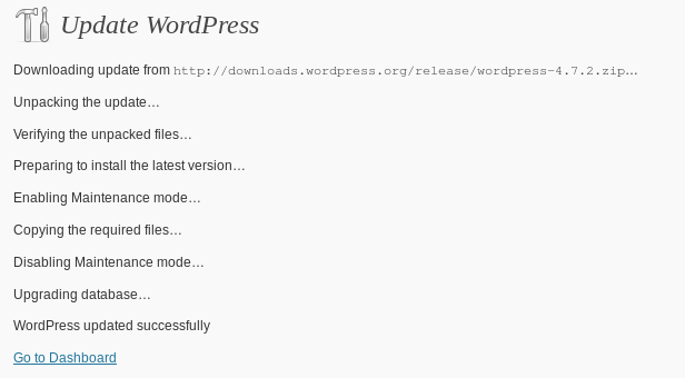
And you get something like this:

And now revert the damage made above: Shut down vsftpd (and verify port 21 is closed), fix the ownership of the sitemirror directory, and restore the ownership of the home directory.
Then remove the sitemirror user (but not its home directory, obviously).
This is for upgrading the local mirror blog. On the real blog, it was just clicking on the button for upgrading. No questions asked about FTP or anything like that.
But the irony is that after upgrading (to 4.7.2), I attempted to publish this post, but “Publish” button was inactive, and the editor stuck on “Saving Draft…”. To double the irony, I upgraded just because one has to, as a security measure. All was fine.
Oddly enough, I didn’t have a similar problem with the (upgraded) mirrored blog.
I wrote a separate post on how I worked around this issue.
How I love upgrading. Actually, I love downgrading more.
What’s this?
This is a note for myself, in case I need a quick replacement for my ADSL connection on the desktop computer (Fedora 12, and oldie). It may seem paradoxical that I’ll read this in order to access the internet (…), but this is probably where I would look first. With my cellphone, which is also the temporary access point, that is.
In short, there’s a lot of stuff here particular to my own computer.
I’m using the small TP-LINK dongle (TL-WN725N), which is usually doing nothing in particular.
Notes to self
- This post is also on your local blog (copy-paste commands…)
- wlan1 is the Access Point dongle (maybe use it instead…?)
- Put the phone in the corner next to the door (that’s where I get a 4G connection) once the connection is established…
- … but not before that, so you won’t run back and forth
Setting up the interface
# service ADSL off
# /etc/sysconfig/network-scripts/firewall-wlan0
# ifconfig wlan0 up
# wpa_supplicant -B -Dwext -iwlan0 -c/etc/wpa_supplicant/wpa_supplicant.conf
ioctl[SIOCSIWAP]: Operation not permitted
# iwlist wlan0 scan
wlan0     Scan completed :
          Cell 01 - Address: 00:34:DA:3D:F8:F5
                    ESSID:"MYPHONE"
                    Protocol:IEEE 802.11bgn
                    Mode:Master
                    Frequency:2.462 GHz (Channel 11)
                    Encryption key:on
                    Bit Rates:108 Mb/s
                    Extra:rsn_ie =30140100000fac040100000fac040100000fac020c00
                    IE: IEEE 802.11i/WPA2 Version 1
                        Group Cipher : CCMP
                        Pairwise Ciphers (1) : CCMP
                        Authentication Suites (1) : PSK
                    IE: Unknown: DD5C0050F204104A0001101044000102103B00010310470010A7FED45DE0455F5DB64A55553EB96669102100012010230001201024000120104200012010540008000000000000000010110001201008000221481049000600372A000120
                    Quality:0  Signal level:0  Noise level:0

# iwconfig wlan0 essid MYPHONE
# dhclient wlan0 &
Note that wpa_supplicant complained, and it was still fine. Use the -d or -dd flags for some debugging info.
It seems like the iwconfig is redundant, as wpa_supplicant handles this, thanks to the “scan_ssid=1″ attribute in the config entry (?). The DHCP client isn’t redundant, because the routing table isn’t set correctly without it (making wlan0 the default gateway)
Shutting down
WPA supplicant config file
The WPA supplicant scans wlan0 and finds matching SSIDs. If such is found, it sends the password. Looks like it handles the association.
/etc/wpa_supplicant/wpa_supplicant.conf should read:
ctrl_interface=/var/run/wpa_supplicant
ctrl_interface_group=wheel

network={
  ssid="MYPHONE"
  scan_ssid=1
  key_mgmt=WPA-PSK
  psk="MYPASSWORD"
}
(it’s already this way)
I needed to update a lot of releases, each designated by a tag, with a single fix, which took the form of a commit. This commit was marked with the tag “this”.
#!/bin/bash
for i in $(git tag | grep 2.0) ; do
 git checkout $i
 git cherry-pick this
 git tag -d $i
 git tag $i
done
This bash script checks out all tags that match “2.0″, and advances it after cherry-picking. Recommended to try it on a cloned repo before going for the real thing, or things can get sad.
These are messy, random notes that I took while setting up my little Raspberry Pi 3. Odds are that by the time you read this, I’ve replaced it with a mini-PC. So if you ask a question, my answer will probably be “I don’t remember”.
Even though the Pi is cool, it didn’t supply what I really wanted from it, which is simultaneous output on SDTV and HDMI. It also turns out that it’s unable to handle a large portion of the video streams and apps out there on the web, seemingly because the lack of processing power vs. the resolution of these streams (running Kodi, which I suppose is the best optimized application for the Pi). So as a catch-all media center attached to a TV set, it’s rather useless.
Starting
- Used the 2016-11-25-raspbian-jessie.zip image
- Raspbian: To get remote access over ssh, do “service ssh start” and login as “pi” with password “raspberry”. Best to remove these before really working. To make ssh permanent, go
# systemctl enable ssh
- Cheap USB charger from Ebay didn’t hold the system up, and a reboot occurred every time the system attempted to boot up. The original LG G4 charger is strong enough, though.
- Kodi installed cleanly with
# apt-get update
# apt-get install --install-suggests kodi
# apt-get install --install-suggests vlc
- … but it seems like vlc doesn’t use video acceleration, and I tried a lot to make it work. It didn’t. So it’s quite useless.
- Enabling Composite output: Use a four-lead 3.5mm plug (a stereo plug doesn’t work). The Samsung screen refused to work, but Radiance detected the signal OK.
I used old Canon Powershot’s video cable, but attached to the RED plug for video, and not the yellow.
In /boot/config.txt, uncomment
sdtv_mode=2
however composite video is disabled when an HDMI monitor is detected, and Q&A’s on the web seem to suggest that simultaneous outputs is not possible. Following this page, I tried setting (so that the HDMI output matches)
hdmi_group=1
hdmi_mode=21
and got 576i (PAL) on the HDMI output but the signals on the composite output were dead (checked with a scope).
- Added “eli” as a user:
# adduser --gid 500 --uid 1010 eli
- Add “eli as sudoer”. Add the file /etc/sudoers.d/010_eli-nopasswd saying
eli ALL=(ALL) NOPASSWD: ALL
- Manually edit /etc/groups, find all the places it says “pi” and add “eli” — so they have some groups. Compare “id” outputs.
- Add ssh keys for password-less access (use ssh-copy-id)
- Change the timezone
$ sudo raspi-config
pick “4 Internationalisation Options” and change the timezone to Jerusalem
- Set “eli” as the default login: One possibility would have been to change the config script (usr/bin/raspi-config) as suggested on this page. Or change /etc/lightdm/lightdm.conf so it says
autologin-user=eli
as for console login, the key line in raspi-config is
ln -fs /etc/systemd/system/autologin@.service /etc/systemd/system/getty.target.wants/getty@tty1.service
so the change is to edit /etc/systemd/system/autologin@.service so it says
ExecStart=-/sbin/agetty --autologin eli --noclear %I $TERM
- Turn off scrrensaver / blanking: First check the current situation (from an ssh session, therefore specific about display)
$ xset -display :0 q
Keyboard Control:
  auto repeat:  on    key click percent:  0    LED mask:  00000000
  XKB indicators:
    00: Caps Lock:   off    01: Num Lock:    off    02: Scroll Lock: off
    03: Compose:     off    04: Kana:        off    05: Sleep:       off
    06: Suspend:     off    07: Mute:        off    08: Misc:        off
    09: Mail:        off    10: Charging:    off    11: Shift Lock:  off
    12: Group 2:     off    13: Mouse Keys:  off
  auto repeat delay:  500    repeat rate:  33
  auto repeating keys:  00ffffffdffffbbf
                        fadfffefffedffff
                        9fffffffffffffff
                        fff7ffffffffffff
  bell percent:  50    bell pitch:  400    bell duration:  100
Pointer Control:
  acceleration:  20/10    threshold:  10
Screen Saver:
  prefer blanking:  yes    allow exposures:  yes
  timeout:  600    cycle:  600
Colors:
  default colormap:  0x20    BlackPixel:  0x0    WhitePixel:  0xffffff
Font Path:
  /usr/share/fonts/X11/100dpi/:unscaled,/usr/share/fonts/X11/75dpi/:unscaled,/usr/share/fonts/X11/Type1,/usr/share/fonts/X11/100dpi,/usr/share/fonts/X11/75dpi,built-ins
DPMS (Energy Star):
  Standby: 600    Suspend: 600    Off: 600
  DPMS is Enabled
  Monitor is On
So turn it off, according to this thread. Edit /etc/kbd/config to say (in different places of the file)
BLANK_TIME=0
POWERDOWN_TIME=0
and then append these lines to ~/.config/lxsession/LXDE-pi/autostart (this is a per-user thing):
@xset s noblank
@xset s off
@xset -dpms
More jots
Kodi setup
- Change setting level to Advanced
- System > Settings > Enable TV
- System > Settings > System > Power savings, set Shutdown function to Minimise (actually, it didn’t help regarding the blackout of the screen on exit)
- Enable and Configure PVR IPTV Simple Client
- On exit, use Ctrl-Alt-F1 and then Ctrl-Alt-F7 to get back from the blank screen it leaves (/bin/chvt should do this as well?)
Video issues
I wanted to get a simultaneous SDTV / HDMI output. Everyone says it’s impossible, but I wanted to give it a try. I mean, it’s the drivers that say no-no, but one can find a combination of registers that gets it working. The alternative is an external HDMI splitter, and then an HDMI to CVBS converter. Spoiler: I gave up in the end. Not saying it’s impossible, only that it’s not worth the bother. So:
Broadcom implements the OpenMAX API, which seems to have a limited set of GPGPU capabilities. For example see firmware/opt/vc/src/hello_pi/hello_fft/ in Raspberry’s official git repo. The QPU is documented in VideoCoreIV-AG100-R.pdf, and there’s an open source assembler for it, vc4asm. and possibly this one is better, mentioned on this page. Also look at this blog.
This page details the VideoCore interface for Raspberry.
An utility for switching between HDMI/SDTV outputs (in hindsight, I would go for the official tvservice instead, but this is what I did):
$ git clone https://github.com/adammw/rpi-output-swapper.git
But that didn’t work:
eli@raspberrypi:~/rpi-output-swapper $ make
cc -Wall -DHAVE_LIBBCM_HOST -DUSE_EXTERNAL_LIBBCM_HOST -DUSE_VCHIQ_ARM -I/opt/vc/include/ -I/opt/vc/include/interface/vcos/pthreads -I./ -g -c video_swap.c -o video_swap.o -Wno-deprecated-declarations
cc -o video_swap.bin -Wl,--whole-archive video_swap.o -L/opt/vc/lib/ -lbcm_host -lvcos -lvchiq_arm -Wl,--no-whole-archive -rdynamic
rm video_swap.o
eli@raspberrypi:~/rpi-output-swapper $ sudo ./video_swap.bin --status
failed to connect to tvservice
which comes from this part in tvservice_init():
    if ( vc_vchi_tv_init( vchi_instance, &vchi_connections, 1) != 0) {
        fprintf(stderr, "failed to connect to tvservice\n");
        exit(-4);
    }
which is implemented in userland/interface/vmcs_host/vc_vchi_tvservice.c, header file vc_tvservice.h in same directory (Raspberry’s official git repo).
After a lot of back and forth, I compared with the official repo’s tvservice utitlity and discovered that it doesn’t check vc_vhci_tv_init()’s return value. So I ditched the check on video_swap as well, and it worked. But the results on the screen were so messy, that I didn’t want to pursue this direction.
In what follows, some things I found out while trying to solve the problem: The program opens /dev/vchiq on bcm_host_init(), and performs a lot of ioctl()’s on it. The rest of tvservice_init() until the error message causes no system calls at all!
/dev/vchiq had major/minor 248/0 on my system. According to /proc/devices, it belongs to the vchiq module (not a big surprise…). Drivers are at drivers/misc/vc04_services/interface/vchiq_arm/ Seemingly with vchiq_arm.c as the top level file, and are enabled with CONFIG_BCM2708_VCHIQ.
There’s a utility, vcgencmd , for setting a lot of different things, log levels among them, but I didn’t manage to figure out where the log messages go to.
Motivation
Somewhere at the bottom of ISE’s xst synthesizer’s report, it says what the maximal frequency is, along with an outline the slowest path. This is a rather nice feature, in particular when attempting to optimize a specific module. There is no such figure given after a regular Vivado synthesis, possibly because the guys at Xilinx thought this “maximal frequency” could be misleading. If so, they had two good reasons for that:
- There is no such thing as a “maximal frequency”: The tools pay attention to the timing constraints and do their best accordingly. Put shortly, you might not get frequency X unless you ask for it.
- In a typical design, there are many clocks with different frequencies. The slowest path might belong to a clock that’s slow anyhow.
And still, it’s sometimes useful to get an idea of where things stand before the Via Dolorosa of a full implementation.
How to do it in Vivado
First and foremost: Set the timing constraints according to your expectations. Or at least, in a way that makes it clear which clock is important, and which can be slow. Then synthesize the design.
After the synthesis has completed successfully, open the synthesized design (clicking “Open Synthesized Design” on the left bar or with the Tcl command “open_run synth_1″).
In the Tcl window, issue the command
report_timing_summary -file mytiming.rpt
which writes a full post-synthesis timing report into mytiming.rpt. Just “report_timing_summary” prints it out to the console.
There’s also a “Report Timing Summary” option under “Synthesized Design” on the left bar, but I find it difficult to navigate my way to getting information in the GUI representation of the report.
Reading the report
RULE #1: The synthesis report is no more than a rough estimation. The routing delays are guesses. It might report timing failures where the implementation will succeed to fix things, and it might say all is fine where the implementation will fail colossally (in particular when the FPGA’s logic usage goes close to 100%).
Now to action: The first thing to look at is the clock summary and Intra Clock Table, and get to know how Vivado has named which clock. For example,
------------------------------------------------------------------------------------------------
| Clock Summary
| -------------
------------------------------------------------------------------------------------------------

Clock                  Waveform(ns)         Period(ns)      Frequency(MHz)
-----                  ------------         ----------      --------------
clk_fpga_1             {0.000 5.000}        10.000          100.000
gclk                   {0.000 4.000}        8.000           125.000
  audio_mclk_OBUF      {0.000 41.667}       83.333          12.000
  clk_fb               {0.000 20.000}       40.000          25.000
  vga_clk_ins/clk_fb   {0.000 20.000}       40.000          25.000
  vga_clk_ins/clkout0  {0.000 1.538}        3.077           325.000
  vga_clk_ins/clkout1  {0.000 7.692}        15.385          65.000
  vga_clk_ins/clkout2  {0.000 7.692}        15.385          65.000

------------------------------------------------------------------------------------------------
| Intra Clock Table
| -----------------
------------------------------------------------------------------------------------------------

Clock                      WNS(ns)      TNS(ns)  TNS Failing Endpoints  TNS Total Endpoints      WHS(ns)      THS(ns)  THS Failing Endpoints  THS Total Endpoints     WPWS(ns)     TPWS(ns)  TPWS Failing Endpoints  TPWS Total Endpoints
-----                      -------      -------  ---------------------  -------------------      -------      -------  ---------------------  -------------------     --------     --------  ----------------------  --------------------
clk_fpga_1                   3.791        0.000                      0                12474        0.135        0.000                      0                12474        3.750        0.000                       0                  5021
gclk                                                                                                                                                                     6.751        0.000                       0                     2
  audio_mclk_OBUF                                                                                                                                                       76.667        0.000                       0                     1
  clk_fb                                                                                                                                                                12.633        0.000                       0                     2
  vga_clk_ins/clk_fb                                                                                                                                                    38.751        0.000                       0                     2
  vga_clk_ins/clkout0                                                                                                                                                    1.410        0.000                       0                    10
  vga_clk_ins/clkout1       10.747        0.000                      0                  215       -0.029       -0.229                      8                  215        6.712        0.000                       0                   195
  vga_clk_ins/clkout2        3.990        0.000                      0                  415        0.135        0.000                      0                  415        7.192        0.000                       0                   211
If the clock frequencies listed in the Clock Summary (which are derived from the timing constraints) don’t help matching between a clock and a name, the TNS Total Endpoints of each clock in the Intra Clock Table helps telling which clock is which. So once the name of the clock of interest is nailed down, search for it in the file, and find something like this:
Max Delay Paths
--------------------------------------------------------------------------------------
Slack (MET) :             3.791ns  (required time - arrival time)
  Source:                 xillybus_ins/xillybus_core_ins/unitw_1_ins/unitw_1_offset_limit_1/C
                            (rising edge-triggered cell FDRE clocked by clk_fpga_1  {rise@0.000ns fall@5.000ns period=10.000ns})
  Destination:            xillybus_ins/xillybus_core_ins/unitw_1_ins/unitw_1_end_offset_0/D
                            (rising edge-triggered cell FDRE clocked by clk_fpga_1  {rise@0.000ns fall@5.000ns period=10.000ns})
  Path Group:             clk_fpga_1
  Path Type:              Setup (Max at Slow Process Corner)
  Requirement:            10.000ns  (clk_fpga_1 rise@10.000ns - clk_fpga_1 rise@0.000ns)
  Data Path Delay:        6.077ns  (logic 2.346ns (38.605%)  route 3.731ns (61.395%))
  Logic Levels:           8  (CARRY4=3 LUT3=1 LUT4=1 LUT6=3)
  Clock Path Skew:        -0.040ns (DCD - SCD + CPR)
    Destination Clock Delay (DCD):    0.851ns = ( 10.851 - 10.000 )
    Source Clock Delay      (SCD):    0.901ns
    Clock Pessimism Removal (CPR):    0.010ns
  Clock Uncertainty:      0.154ns  ((TSJ^2 + TIJ^2)^1/2 + DJ) / 2 + PE
    Total System Jitter     (TSJ):    0.071ns
    Total Input Jitter      (TIJ):    0.300ns
    Discrete Jitter          (DJ):    0.000ns
    Phase Error              (PE):    0.000ns

    Location             Delay type                Incr(ns)  Path(ns)    Netlist Resource(s)
  -------------------------------------------------------------------    -------------------
                         (clock clk_fpga_1 rise edge)
                                                      0.000     0.000 r
                         PS7                          0.000     0.000 r  xillybus_ins/system_i/vivado_system_i/processing_system7_0/inst/PS7_i/FCLKCLK[1]
                         net (fo=1, unplaced)         0.000     0.000    xillybus_ins/system_i/vivado_system_i/processing_system7_0/inst/n_707_PS7_i
                         BUFG (Prop_bufg_I_O)         0.101     0.101 r  xillybus_ins/system_i/vivado_system_i/processing_system7_0/inst/buffer_fclk_clk_1.FCLK_CLK_1_BUFG/O
                         net (fo=5023, unplaced)      0.800     0.901    xillybus_ins/xillybus_core_ins/bus_clk_w
                                                                      r  xillybus_ins/xillybus_core_ins/unitw_1_ins/unitw_1_offset_limit_1/C
  -------------------------------------------------------------------    -------------------
                         FDRE (Prop_fdre_C_Q)         0.496     1.397 f  xillybus_ins/xillybus_core_ins/unitw_1_ins/unitw_1_offset_limit_1/Q
                         net (fo=5, unplaced)         0.834     2.231    xillybus_ins/xillybus_core_ins/unitw_1_ins/unitw_1_offset_limit[1]
                         LUT4 (Prop_lut4_I0_O)        0.289     2.520 r  xillybus_ins/xillybus_core_ins/unitw_1_ins/Mcompar_n0037_lutdi/O
                         net (fo=1, unplaced)         0.000     2.520    xillybus_ins/xillybus_core_ins/unitw_1_ins/Mcompar_n0037_lutdi
                         CARRY4 (Prop_carry4_DI[0]_CO[3])
                                                      0.553     3.073 r  xillybus_ins/xillybus_core_ins/unitw_1_ins/Mcompar_n0037_cy[0]_CARRY4/CO[3]
                         net (fo=1, unplaced)         0.000     3.073    xillybus_ins/xillybus_core_ins/unitw_1_ins/Mcompar_n0037_cy[3]
                         CARRY4 (Prop_carry4_CI_CO[3])
                                                      0.114     3.187 r  xillybus_ins/xillybus_core_ins/unitw_1_ins/Mcompar_n0037_cy[4]_CARRY4/CO[3]
                         net (fo=3, unplaced)         0.936     4.123    xillybus_ins/xillybus_core_ins/unitw_1_ins/Mcompar_n0037_cy[7]
                         LUT6 (Prop_lut6_I4_O)        0.124     4.247 f  xillybus_ins/xillybus_core_ins/unitw_1_ins/unitw_1_wr_request_condition/O
                         net (fo=7, unplaced)         0.480     4.727    xillybus_ins/xillybus_core_ins/unitw_1_ins/unitw_1_wr_request_condition
                         LUT3 (Prop_lut3_I2_O)        0.124     4.851 r  xillybus_ins/xillybus_core_ins/unitw_1_ins/unitw_1_flush_condition_unitw_1_wr_request_condition_AND_179_o3_lut/O
                         net (fo=1, unplaced)         0.000     4.851    xillybus_ins/xillybus_core_ins/unitw_1_ins/unitw_1_flush_condition_unitw_1_wr_request_condition_AND_179_o3_lut
                         CARRY4 (Prop_carry4_S[2]_CO[3])
                                                      0.398     5.249 f  xillybus_ins/xillybus_core_ins/unitw_1_ins/unitw_1_flush_condition_unitw_1_wr_request_condition_AND_179_o2_cy_CARRY4/CO[3]
                         net (fo=21, unplaced)        0.979     6.228    xillybus_ins/xillybus_core_ins/unitw_1_ins/unitw_1_flush_condition_unitw_1_wr_request_condition_AND_179_o
                         LUT6 (Prop_lut6_I5_O)        0.124     6.352 r  xillybus_ins/xillybus_core_ins/unitw_1_ins/_n03401/O
                         net (fo=15, unplaced)        0.502     6.854    xillybus_ins/xillybus_core_ins/unitw_1_ins/_n0340
                         LUT6 (Prop_lut6_I5_O)        0.124     6.978 r  xillybus_ins/xillybus_core_ins/unitw_1_ins/unitw_1_end_offset_0_rstpot/O
                         net (fo=1, unplaced)         0.000     6.978    xillybus_ins/xillybus_core_ins/unitw_1_ins/unitw_1_end_offset_0_rstpot
                         FDRE                                         r  xillybus_ins/xillybus_core_ins/unitw_1_ins/unitw_1_end_offset_0/D
  -------------------------------------------------------------------    -------------------

                         (clock clk_fpga_1 rise edge)
                                                     10.000    10.000 r
                         PS7                          0.000    10.000 r  xillybus_ins/system_i/vivado_system_i/processing_system7_0/inst/PS7_i/FCLKCLK[1]
                         net (fo=1, unplaced)         0.000    10.000    xillybus_ins/system_i/vivado_system_i/processing_system7_0/inst/n_707_PS7_i
                         BUFG (Prop_bufg_I_O)         0.091    10.091 r  xillybus_ins/system_i/vivado_system_i/processing_system7_0/inst/buffer_fclk_clk_1.FCLK_CLK_1_BUFG/O
                         net (fo=5023, unplaced)      0.760    10.851    xillybus_ins/xillybus_core_ins/bus_clk_w
                                                                      r  xillybus_ins/xillybus_core_ins/unitw_1_ins/unitw_1_end_offset_0/C
                         clock pessimism              0.010    10.861
                         clock uncertainty           -0.154    10.707
                         FDRE (Setup_fdre_C_D)        0.062    10.769    xillybus_ins/xillybus_core_ins/unitw_1_ins/unitw_1_end_offset_0
  -------------------------------------------------------------------
                         required time                         10.769
                         arrival time                          -6.978
  -------------------------------------------------------------------
                         slack                                  3.791
This is a rather messy piece of text, but the key elements are marked in red.
Before drawing any conclusions, make sure it’s the right part you’re looking at:
- It’s the Max Delay Paths section. The mimimal paths section is useful for spotting hold time violation, and has no effect on the maximal frequency.
- It’s the right clock. In the example above, it’s clk_fpga_1. The Requirement line states not only the constraint given for this clock (10 ns = 100 MHz), but also that it goes from one rising edge of clk_fpga_1 to another.
Once that’s done, let’s see what we’ve got: The requirement was 10 ns, and the slack 3.791 ns (note that it’s positive), which means that we could have asked for a clock period 3.791 ns shorter and it would still be OK. So it could have been 10 – 3.791 = 6.2090 ns, which is some 161 MHz.
So the short answer to the “maximal clock” question for clk_fpga_1 is 161 MHz. But remember that this figure might change if the constraints change.
And a final note: The Data Path Delay tells us something about what made this worst path slow or fast. How much delay went on logic, and how much on the (estimated) route delays. So does the detailed delay report that follows. For a more detailed report, consider using the “-noworst” flag when requesting the timing report, so a few worst-case paths are listed. This can help solving timing problems.
It’s quite well-known, that in order to call a function in C, which has been compiled in a C++ source file, there’s need for an extern “C” statement.
So if this appears on a C++ source file:
void my_puts(const char *str) {
 ...
}
and there’s an attempt to call my_puts() in a plain C file, this will fail with a normal compiler as well as HLS.
In HLS, specifically, the function call in the C file will yield an error like
ERROR: [SYNCHK 200-71] myproject/example/src/main.c:20: function 'my_puts' has no function body.
The thing is, that just adding an extern “C” in the .cpp file will not be enough. The “no function body” error will not go away. What’s required is setting the namespace to hls as well. Something like this:
namespace hls {

extern "C" {

void my_puts(const char *str) {
 ...
}

}
}
The inspiration for this solution came from the source files of the HLS suite itself. I don’t know if this is really a good idea, only that it works.
If you’re into Linux, and you ever find yourself in a place you’d like to return to with Waze (in the middle of some road, or some not-so-well-mapped village, a campus etc.), just take a photo with your cellular. Assuming that it stores the GPS info.
Alternatively, the “My GPS Coordinates” Android app can be usedful to obtain, SMS, and share the coordinates. But I’ll stick to the photo method.
Use exiftool to extract the coordinates from the image. The -c flag makes sure the coordinates are in plain format:
$ exiftool -c "%.6f degrees" 20160328_160309.jpg
ExifTool Version Number         : 8.00
File Name                       : 20160328_160309.jpg
Directory                       : .
File Size                       : 5.2 MB
File Modification Date/Time     : 2016:06:14 15:43:43+03:00
File Type                       : JPEG
MIME Type                       : image/jpeg

[ ... ]

GPS Altitude                    : 0 m Above Sea Level
GPS Date/Time                   : 2016:03:28 13:02:58Z
GPS Latitude                    : 32.777351 degrees N
GPS Longitude                   : 35.024139 degrees E
GPS Position                    : 32.777351 degrees N, 35.024139 degrees E
Image Size                      : 5312x2988
Shutter Speed                   : 1/50

[ ... ]
Aha! Now a manual edit of the part marked in red. The link is
https://maps.google.com/?ll=32.777351,35.024139
I’m lucky enough to live in the North-East part of the world. Had it been south or west, just put negative numbers.
Or, create a Waze link, which can be tapped on the phone to get me to that place:
http://waze.to/?ll=32.777351,35.024139&navigate=yes
This opens the web browser, which in turn opens Waze, which started telling me what to do to get there…
The following link can also be used to open Waze directly, however it has to be part of a link on a page like this:
waze://?ll=32.777351,35.024139
As plain text on a mail message, SMS or in Kepp, it didn’t work on my LG G4 Android, because the “waze:” prefix didn’t turn it into a link in these apps. It’s still useful within a website (or an HTMLed web message?)